Row house 2002 · somewhere in the Randstad (NL) · design v8, 4 November 2026
District heating out, Haier AW062 monobloc in: who will review my design and 13 open questions?
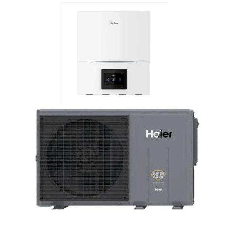
I'm replacing disconnected district heating (Eneco) with a Haier AW062MUGHA monobloc (6 kW, R290) with the ATW-A03N control box and the HW-WA101DBT wired controller. Hydraulics: Haier → 3-way valve → (a) a Haier WT60V 60 L buffer, connected in parallel (4 ports), with a second pump to 6 Jaga convectors, and (b) a Haier WT200V 200 L DHW tank (2.0 m² coil, 2.5 kW element). Room control stays Honeywell Evohome; the BDR91 goes volt-free to CN13 ZONE1 ON/OFF. An installation company does all the work (ISDE subsidy).
The Haier documentation leaves a few things open. Does anyone have experience with the ATW-A03N / HW-WA101DBT, or with a similar setup? The house has no heating and no hot water right now, so every tip helps.
How to reply: in the forum thread, with the question number (e.g. “V7: on mine K is 230 V during hot water, valve X …”). The numbers are the same as on the Dutch page (V = vraag, question). Click a number such as V7 to copy a direct link to that question, or use the reply template.
18 GJ/yearreal district-heating use (≈ 5,000 kWh), steady for 4 years
≈ 2–3 kWpeak demand on the coldest day (from the real use)
60 L + 200 Lparallel WT60V buffer + WT200V DHW tank
6 Jaga'sconvectors, designed for ≈ 70 °C
3 × 25 Agrid connection; panel full → separate heat-pump sub-panel
The 13 questions
Under each question: where the background is on this page, and which pages of the Haier documents I have already read. IM = R290 Monobloc installation manual (22-01-2025) · DB = Engineering DataBook (SYJS-07-2024 REV.B) · ATW = ATW-A03N installation manual (2025-04-03). Page numbers = printed numbers.
A. ATW-A03N control box and HW-WA101DBT controller
V1 Which tank-sensor input with a single tank sensor: T_tank up (CN50) or T_tank down (CN48)?
The ATW-A03N has two tank inputs: CN50 "T_tank up" and CN48 "T_tank down". The Haier WT200V has only one sensor pocket, low in the element flange. Which input does that one sensor go on? Does the controller show error E10 if the other input stays empty, and do you then have to switch something off in the menu?
Background: ATW-A03N connections · WT200V · schematic part (5). Documents: ATW p. 9 (CN48/CN50) · IM p. 39 (E10) · WT200V p. 6 and 8.
V2 Which setting makes the BDR91 on CN13 ZONE1 ON/OFF work?
I want Evohome (BDR91, volt-free contact) to switch CN13 ZONE1 ON/OFF. The installer menu has "Control Mode of Zone1": Main controller / Third party controller / Thermostat, and "Third Party Controller Type": Type 1 / Type 2. I think: Third party controller, Type 2, with the HEAT/COOL contact left open (= heating). Is that right? Does the compressor stop immediately when ZONE1 opens, or does it finish charging the buffer first?
Background: Evohome · settings. Documents: IM p. 57–58 · DB p. 69 (third-party control, Type 1/2) · ATW p. 11–12.
V3 Short cycling caused by Evohome: any experience with BDR91 → ZONE1 ON/OFF and a parallel buffer?
Even at its lowest setting, Evohome switches the BDR91 3 times per hour (TPI, min. ON 5 min). Has anyone measured whether a Haier then short-cycles, even with a 60 L parallel buffer? My fallback: ZONE1 permanently on in winter, and the BDR91 only switches pump 2 (PUMP1 output → BDR91 COM/NO → pump 2). Is the BDR91 contact suitable for a ≈ 45 W pump at 230 V?
V4 How should the Haier's internal pump be set with a parallel buffer, and does pump 2 keep running during hot-water charging?
"Indoor unit installation" has "Pump Flow Rate Control Mode" (ΔT between out and in water / Constant speed duty out; default Constant speed) and "IDU Pump Duty Out" (0–100 %, default 0 %). What does 0 % mean: maximum, automatic or off? I want a fixed ≈ 1.0 m³/h (primary ≥ secondary). And: does the PUMP1 output (pump 2, radiators) stay on while the tank is being heated?
V5 Does "Schedule" also work for hot water (time window 11:00–15:00)?
I want the tank to heat only between 11:00 and 15:00 (solar panels), but still reheat in the evening if it really runs empty. Can "Schedule" (time block with mode and temperature) do that, e.g. DHW 48 °C from 11 to 15 h and ≈ 41 °C the rest of the day? Or is the SG-ready input (CN47) with a timer switch better?
Background: solar vs. heat pump · settings. Documents: IM p. 49–50 (Schedule), p. 56 (SG Ready), p. 57 (Tank Re-heat Temp.) · ATW p. 11–12.
V6 Energy meter on CN52: which kWh meter with pulse output?
The Haier can show its own consumption with an external pulse meter on CN52 EM ("Pulse Selection for power consumption": 1/10, 1/1, 10/, 100/kWh). Does the HomeWizard 1-phase kWh meter have a pulse output (S0), or should I take an Eastron SDM120? Has anyone connected this?
V7 3-way valve direction: does the Haier put 230 V on K for hot water?
The ATW-A03N has terminals L, N, K ("live, neutral, control") for the 3-way valve. Is K = 230 V during hot water (and K = 0 during space heating)? Haier's own example drawing calls the tank port "A" and the buffer port "B", the opposite of many valves. Which valve do you use with a Haier (e.g. Rekx OKO1, VC6013 type), and did you have to change anything on it?
V8 Floor-heating group without a (known) oxygen barrier: is a plate heat exchanger needed?
The house has an old WTH floor-heating unit (own Grundfos UPS 25-40, thermostatic mixing valve) for the bathroom floor, unused for 4 years. If the blue floor pipe has no oxygen barrier (no print "EVOH / zuurstofdicht / DIN 4726"): is a small plate heat exchanger really needed, or would something else do? And can such a group with its own pump simply go on the secondary side of the buffer (next to the radiators)?
V9 Do the Haier sensors (0150408957) fit the WT200V sensor pocket and the WT60V measuring port?
Has anyone fitted the supplied Haier temperature sensors (part no. 0150408957) into a Haier WT200V (pocket in the flange) and a Haier WT60V (front measuring port)? What is the sensor diameter, and did you need an adapter or thermal paste?
Background: tank & buffer · schematic parts (4) and (5). Documents: DB p. 129 · WT200V p. 8 · WT60V p. 2.
C. Tank element and electrical
V10 Which thermostat of the WT200V element is adjustable (RT or MT), and how high?
According to its wiring diagram, the 2.5 kW element of the Haier WT200V has two thermostats in series: RT ("normal temperature thermostat") and MT (in German "manueller Thermostat"). Which one is adjustable, and up to what temperature? I want the anti-legionella cycle at 60 °C (default is 75 °C), so the adjustable thermostat must be at least 65 °C. Is MT a manual-reset safety cut-out?
Background: WT200V · Sterilization. Documents: WT200V p. 5 (MT/RT/EH/HL) · IM p. 54 (Sterilization 50–75 °C, default Mon 23:00, 75 °C).
V11 Cable type: XMvK/YMvK or H07RN-F to the outdoor unit?
Haier specifies H07RN-F "or the electrically equivalent type" for the power and interconnection cables. Can the fixed run to the front facade be XMvK/YMvK 3 × 4 mm², with only the last flexible part in H07RN-F? What do installers do in practice (NEN 1010)?
Background: sub-panel, E2/E5. Documents: IM p. 7 and from p. 29 · DB p. 19 (min. 4 mm², MCA 13.5 A, MFA 16 A).
D. Other
V12 Jaga convectors at 45–55 °C: enough output in the coldest rooms?
My Jaga's were sized for district heating (≈ 70 °C). The smallest: 10.5 × 72 cm (coldest room, top floor) and 20 × 72 cm. Who has experience with Jaga's at 45–55 °C supply? Is a DBE booster or a bigger Jaga usually needed?
V13 Price check: 20 A RCBO type A, ≥ 30 mm insulation, raised stand
Is ≈ €30–55 right for an RCBO 20 A, 30 mA, type A, 1P+N (Hager ADA920G / ABB DS201 B20 A30), ≈ €60–110 for 10 m of 30 mm insulation, and ≈ €20–50 for a raised stand for the outdoor unit? Where do you buy these cheapest?
Background: parts & cost. Documents: IM p. 26 (insulation ≥ 30 mm), p. 19–20 (placement).
Also welcome: comments on the parts choice (tank, buffer, 3-way valve, pump, anti-freeze valves), or on anything I've completely overlooked.
1. The house and the old situation
Type
Row house, built 2002, somewhere in the Randstad
Living space
145 m² over 3 floors; footprint 12.4 × 5.4 m (≈ 67 m² per floor)
Heated rooms
6: living room, 4 bedrooms/offices, bathroom
Emitters
Jaga convectors, a small bathroom radiator and an existing WTH floor-heating group (unused for 4 years)
Eneco district heating, direct system: the network water went straight through the radiators (no own pump or expansion vessel). Tap water via a plate heat exchanger. Delivery set removed in March 2026; now no heating and no hot water.
Rooms without heating at −6 °C outside
Floor
Room
m²
Temp.
Jaga (h × w)
Control
gr
Living room
43
13 °C
19×140 + 19×135
HR92
1
Parents
21
12 °C
19×92
manual, always open
1
Kid
19
12 °C
9.5×201
HR92
2
Office
23
11 °C
20×72 ⚠
HR92
2
Meditation room
13
10 °C
10.5×72 ⚠
HR92
2
Bathroom
4
14 °C
small, size unknown
T87RF
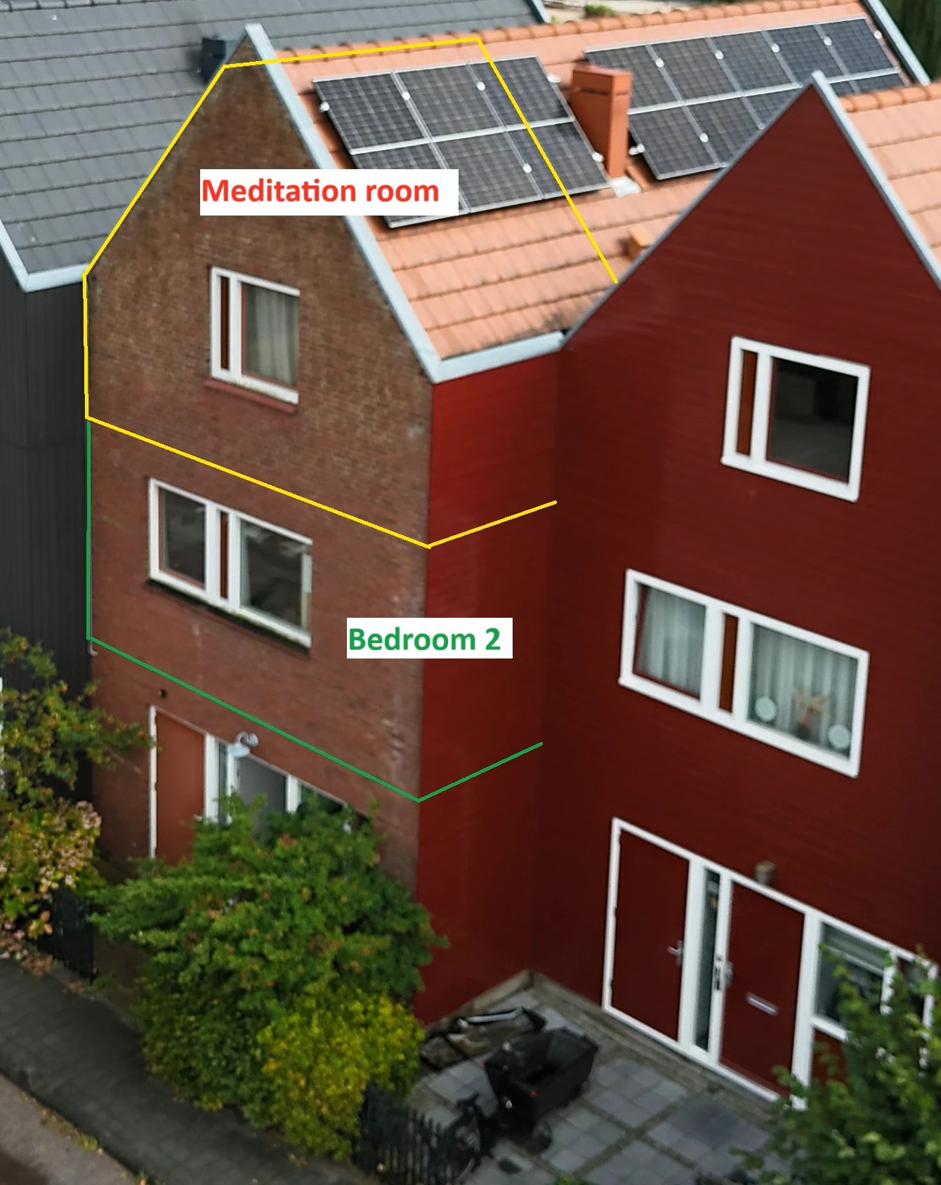
The meditation room is the coldest: it has one more outside wall than the others. The other rooms border heated neighbours.
Front facade from above. Yellow = meditation room (2nd floor, under the roof, coldest room), green = bedroom 2. Solar panels on the roof.
Heat demand from the real consumption
18 GJ/year of district heat (steady for 4 years) = ≈ 5,000 kWh, for space heating and tap water together.
Tap water: 11 showers/week (2 adults, 2 teenagers), 8 L/min → ≈ 970 kWh; kitchen ≈ 225 kWh; losses of the old set ≈ 330 kWh → ≈ 1,530 kWh.
Space heating ≈ 3,470 kWh/year ÷ 1,400–1,800 full-load hours → ≈ 1.9–2.5 kW, with margin 2–3 kW on the coldest day.
A rough per-room estimate (everything 20 °C all day) gives 4.1–5.1 kW at −6 °C; real use is more economical (zoning, cool bedrooms).
The installer will do a heat-loss calculation (ISSO 51).
Haier AW062 (max.)
Water 45 °C
50 °C
55 °C
−7 °C outside
5.2 kW · COP 3.0
4.8 · 2.7
4.3 · 2.4
−10 °C outside
5.0 kW · COP 2.8
4.5 · 2.5
3.9 · 2.2
Source: Engineering DataBook. Minimum output ≈ 1.2–1.6 kW, while the house needs only 0.3–1 kW in spring and autumn. That is why there is a buffer.
The pipes in the meter cupboard
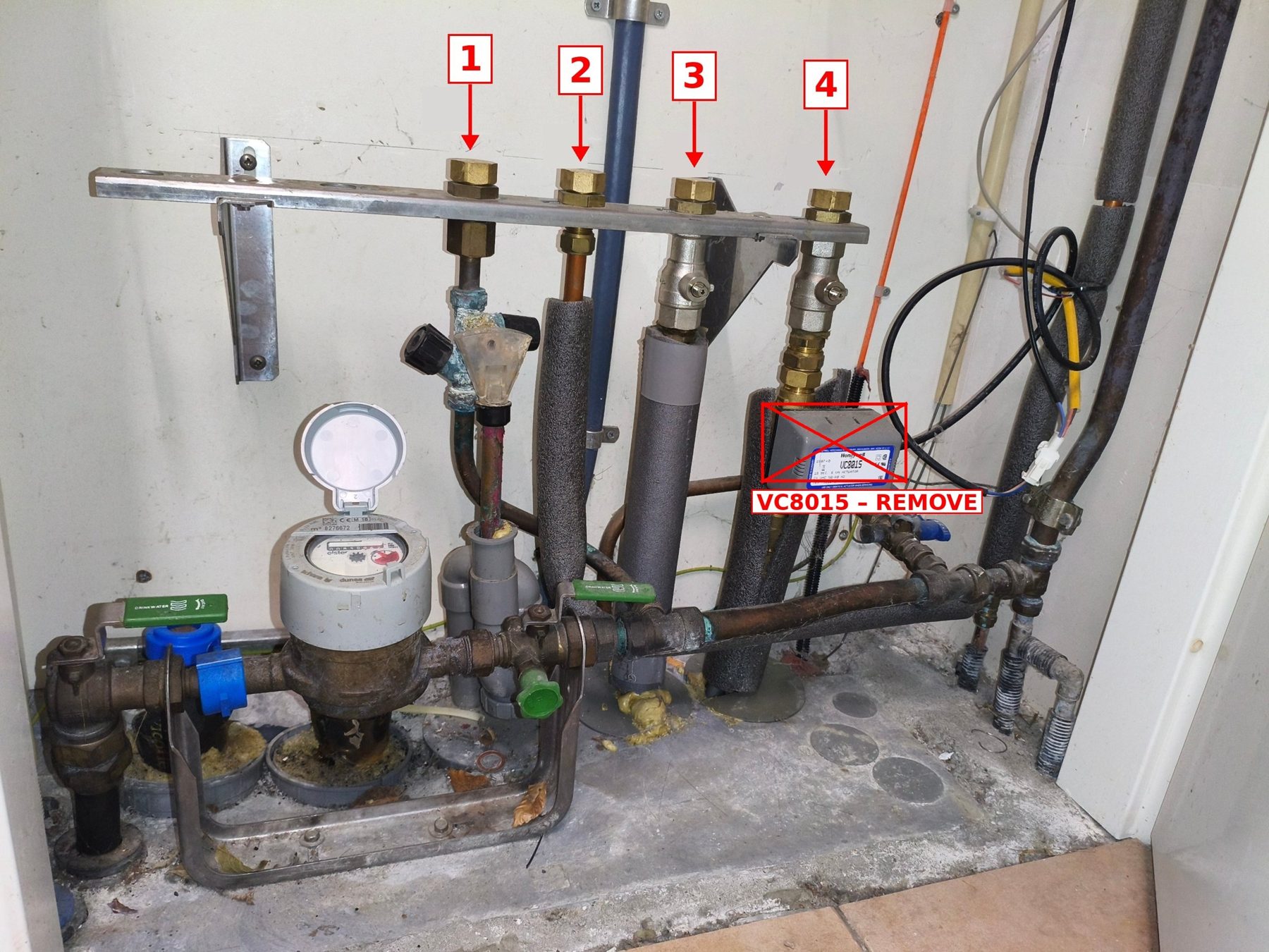
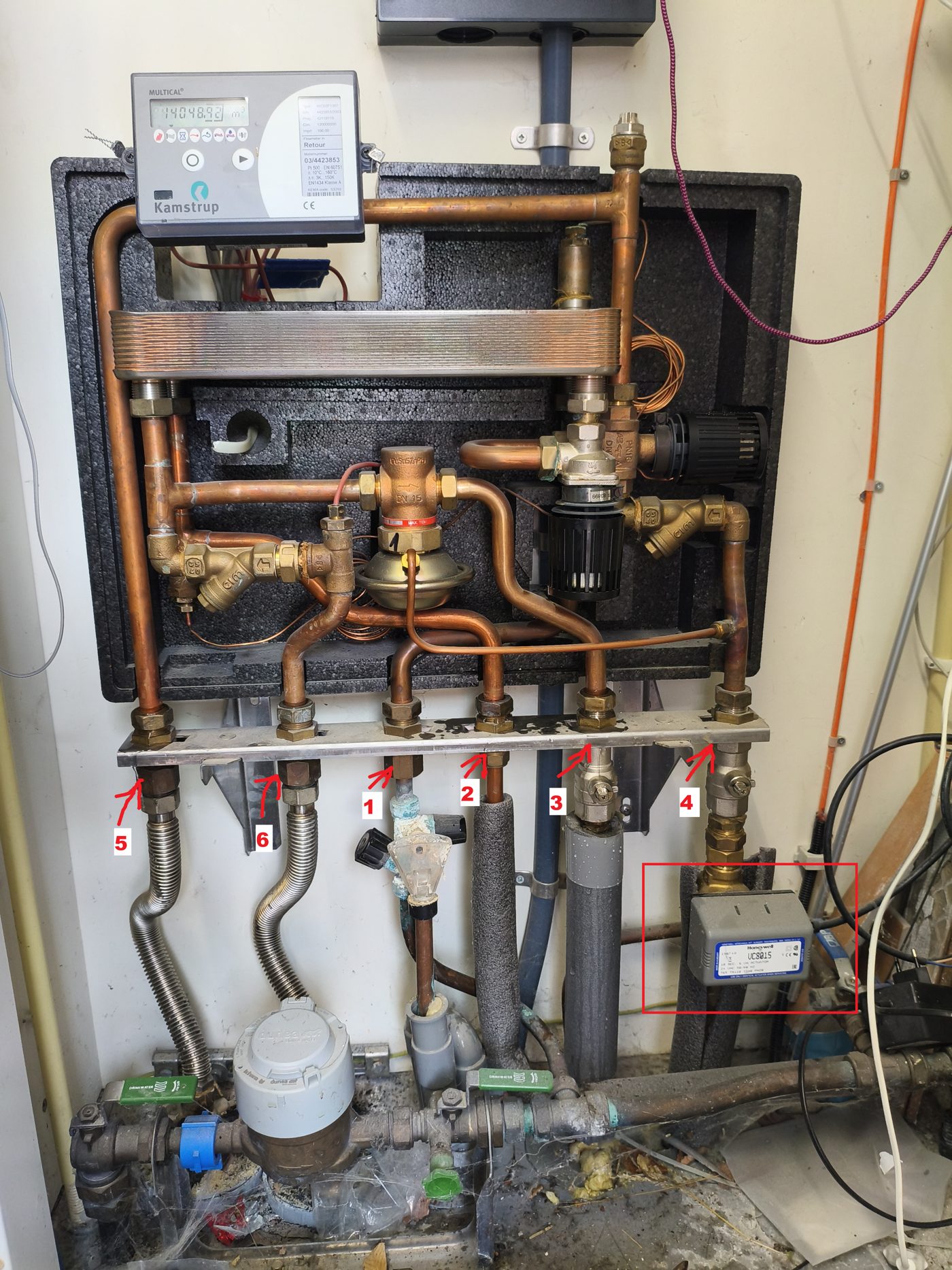
The rail has four capped connections, stamped KW – WW – A – R: 1 cold water in, 2 hot water to the taps, 3 radiator supply, 4 radiator return. The old Honeywell VC8015 zone valve on pipe 4 is replaced by a straight coupling. The fitting under pipe 1 is the old, weeping inlet safety group (inlaatcombinatie); it is replaced, and its drain to the sewer is reused.
2. Hydraulic design (Plan B)
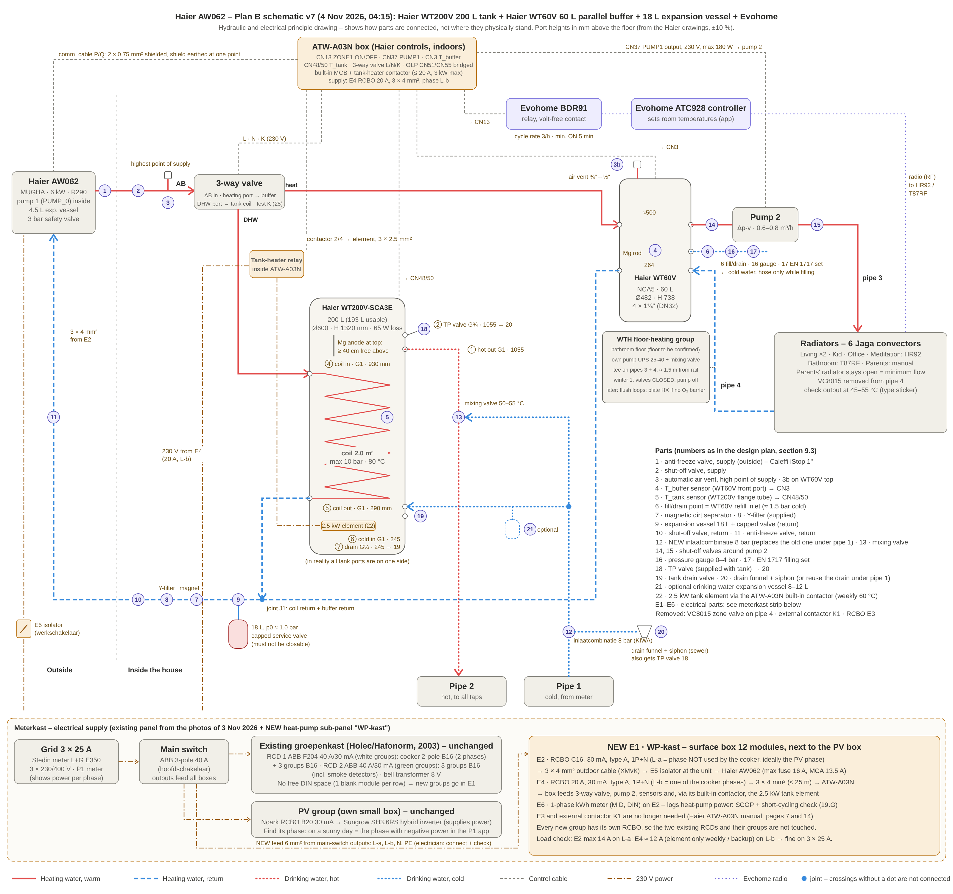
Principle schematic v7 (click to enlarge; click again for 100 %). It shows how everything is connected, not where it stands. Port heights in mm above the floor, from the Haier drawings (±10 %).
Impression of the end result
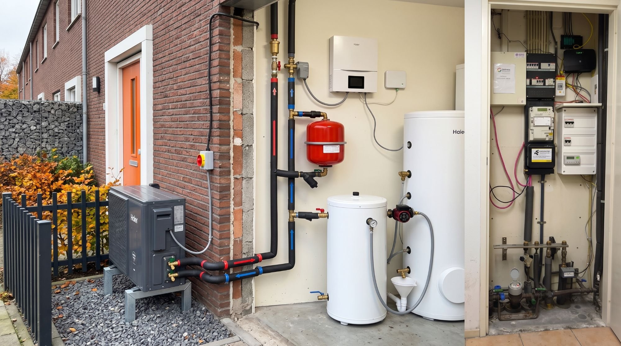
AI impression, not a photo. This is roughly how it should look; nothing has been installed yet. The schematic above is leading.
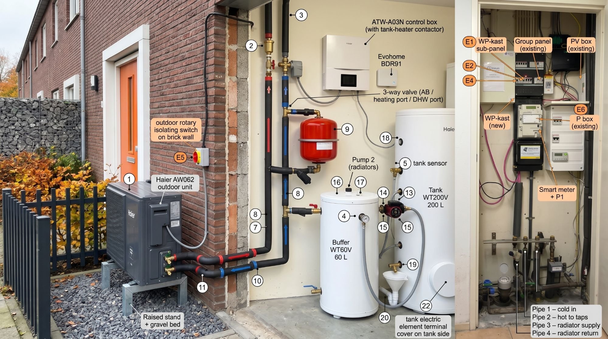
Without numbers. Left the outdoor unit on a raised stand, middle the storage room with buffer and tank, right the meter cupboard.With numbers (roughly following the schematic). Some labels don't match the design: "8" appears twice and "15" three times; "16" and "17" (pressure gauge and filling set) sit on top of the buffer; "4" (the buffer sensor) points at a pressure gauge; "E6" points at an existing box instead of the kWh meter in the new sub-panel. The design itself is fine; only the picture is off.
Principle: two loops with a parallel buffer
Loop 1, Haier ↔ buffer / tank coil. The Haier's internal pump (PUMP_0, "pump 1") runs ≈ 1.0 m³/h. Nothing in loop 1 can close. The 3-way valve sits right after the Haier: heating port → buffer, DHW port → tank coil. Ports are named by function here, because the letters differ per manufacturer (V7).
Loop 2, buffer ↔ radiators. Pump 2 (Wilo Para 25/6, Δp-v, 0.6–0.8 m³/h) draws from the WT60V's upper right port and feeds pipe 3. The return (pipe 4) goes only into the lower right port, never directly into the Haier return.
WT60V 60 L in parallel (4 × 1¼"): separates the loops, covers defrost, and gives ≈ 1 start per hour at low load (6 K switching band ≈ 0.42 kWh per cycle).
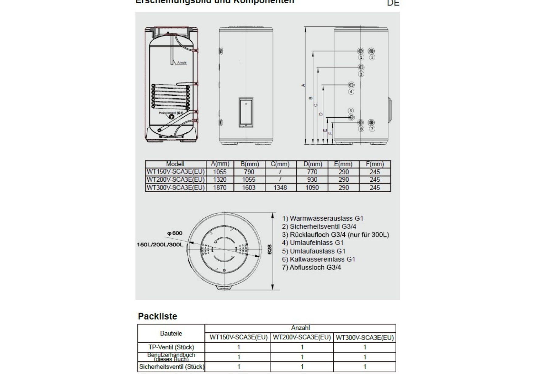
WT200V 200 L: 2.0 m² coil in counter-flow (in at 930 mm, out at 290 mm). Tank at 48 °C, preferably heated between 11 and 15 h. Anti-legionella: Sunday 13:00 to 60 °C, the last degrees by the 2.5 kW element via the built-in relay of the ATW-A03N.
Common return (J1): 18 L expansion vessel (pre-charge 1.0 bar, capped valve) → Dirtmag → Y-filter → Haier.
A specialist who visited on 3 November drew the same principle (photos).
WT200V ⑤ coil out (290 mm) + WT60V lower left (264 mm)
–
J1
tee 28 mm
J1
9 → 7 → 8 → 10 → 11
Haier inlet R1"
Y-filter in flow direction
WT60V upper right
14 → pump 2 → 15
pipe 3
arrow away from the buffer
pipe 4
–
WT60V lower right
only here
pipe 1 (cold)
12 (→ 21)
WT200V ⑥ G1 (245 mm)
adapter 1" × 22 mm
WT200V ① G1 (1,055 mm)
13
pipe 2
–
WT200V ② G¾ (1,055 mm)
18
funnel 20
discharge always open, pointing down
Water volume and expansion vessel
Radiators ≈ 8–14 L, pipes ≈ 15–20 L, buffer 60 L, coil ≈ 10–12 L, Haier + outdoor pipes ≈ 5–10 L → ≈ 100–115 L (phase 2 with floor loops ≈ 130 L). Expansion 10 → 75 °C ≈ 3.0 L + 3.0 L reserve. Static height 6 m → pre-charge 1.0 bar; pe 2.5 bar (safety valve 3 bar) → usable fraction 0.43 → ≈ 14 L total − 4.5 L built-in ≈ 9.5 L → chosen 18 L. Haier: the built-in 4.5 L vessel covers max. 78 L (IM p. 26). Fill pressure 1.5 bar cold, 1.8–2.2 bar warm.
3. Controls: Evohome, ATW-A03N and settings
Role of Evohome
ATC928 + app, HR92's, T87RF
Unchanged: temperature and schedule per room
BDR91
Becomes a boiler relay / heat demand (not a zone valve). COM/NO volt-free to CN13 ZONE1 ON/OFF. The old 24 V wires of the VC8015 come off the contact first. Cycle rate 3/h (lowest), min. ON 5 min.
VC8015 zone valve
Removed (straight coupling), transformer removed
Parents' bedroom
Manual valve stays open = minimum flow for loop 2
Division of tasks
Evohome decides which rooms get heat and whether heat is needed. The Haier decides how warm (heating curve), keeps buffer and tank at temperature and switches pump 2 (CN37 PUMP1).
Connections in the ATW-A03N
Device
Terminal
Note
3-way valve
"3-way Valve" L, N, K (power terminals 1–3)
Expected: K live = DHW, K dead = heating. Not in the documents → V7
Because Evohome was made for gas boilers and switches up to 3 times per hour, I will log the compressor starts with kWh meter E6 for the first 14 days (power > 300 W = one start). Judging at +5 to +12 °C outside:
Result
Meaning
Action
≤ 2 starts/hour and runs ≥ 15 min
Good
Nothing
3–4 starts/hour or runs 10–15 min
Borderline
ΔT for Heating On 6 → 8 K; check the Evohome settings
> 4 starts/hour or runs < 10 min
Short cycling
Also lower the heating curve 1–2 °C; no improvement after 3 days → fallback
Starts exactly when the BDR91 switches
Evohome drives the cycling
Fallback
Fallback: ZONE1 permanently on during the heating season, so the Haier controls on T_buffer only. The BDR91 contact moves into the live of pump 2: CN37 PUMP1 L → BDR91 COM → NO → pump 2. Pump 2 then runs only when the Haier allows it and Evohome asks for heat (V3).
4. WT200V tank and WT60V buffer
Haier WT200V-SCA3E(EU)
Volume
200 L (193 L usable)
Coil
2.0 m², max. 10 bar / 80 °C
Vessel
Enamelled steel, magnesium anode at the top (≥ 40 cm free above)
Pressure
8.5 bar nominal, max. 9.5 bar → 8 bar inlet safety group
Element
2.5 kW, 230 V, thermostats RT + MT in series (V10)
Heat loss
65 W (ErP C)
Size
Ø 600 × 1,320 mm, full ≈ 260 kg
Ports (one side)
① hot G1 1,055 · ② T&P G¾ 1,055 · ④ coil in G1 930 · ⑤ coil out G1 290 · ⑥ cold G1 245 · ⑦ drain G¾ 245 mm · one sensor pocket in the flange
Haier WT60V-NCA5(EU)
Volume
60 L, 8 bar, 0–90 °C
Size
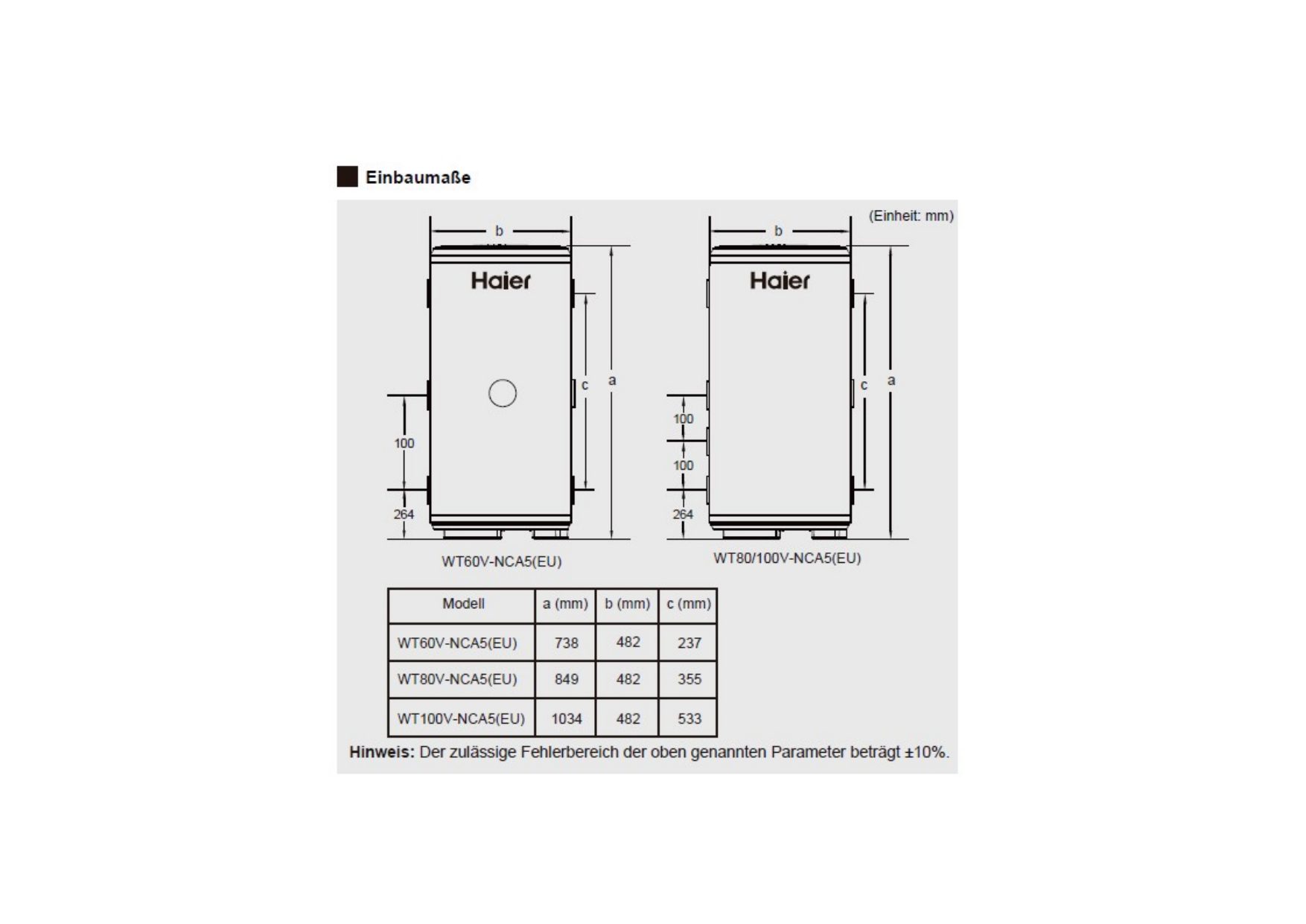
Ø 482 × 738 mm, full ≈ 85 kg, floor-standing, secure with angle brackets
Insulation
50 mm PU, ≈ 39 W at 65 °C (≈ 13–15 W at 35 °C)
Water ports
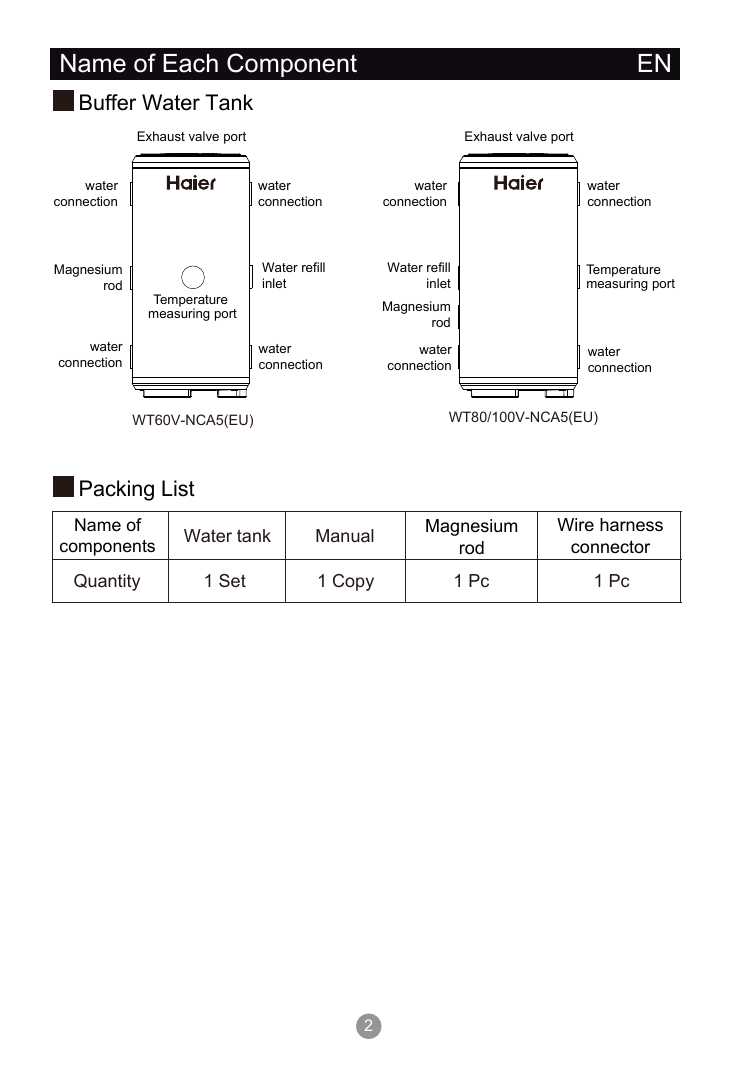
4 × 1¼" F (DN32): UL/UR ≈ 500 mm, LL/LR 264 mm
Other
Air vent at the top ¾" · front measuring port (≈ 380 mm) · refill port · magnesium rod (supplied loose)
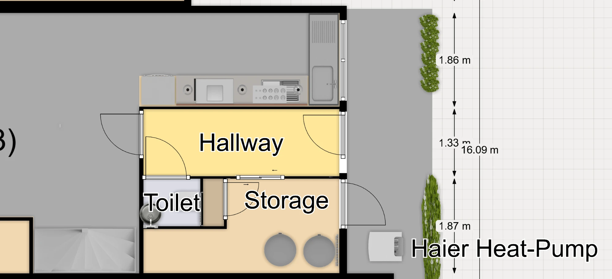
Placement: side by side on the floor in the storage room at the front (floor plan), as close to the meter cupboard as possible (≈ 1.2 m wall width, 0.65 m deep). Stacking the buffer on the tank was ruled out: ≈ 2.6 m high, and the anode can't be reached. A combined tower was ruled out too: no reliable seller.
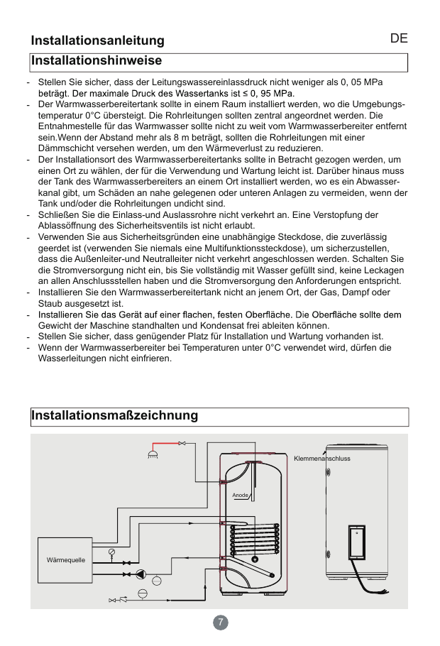
Drinking-water side: new KIWA inlet safety group 8 bar; T&P valve on ②; thermostatic mixing valve 50–55 °C on ① (cold taken after the inlet safety group); weekly anti-legionella cycle ≥ 60 °C. Each heat-up drips ≈ 3 L from the overflow; a drinking-water expansion vessel (21) is optional.
5. Existing floor heating (WTH group)
In a cupboard ≈ 1.5 m from the meter-cupboard pipes is a red WTH floor-heating manifold with its own Grundfos UPS 25-40 180 (30/45/60 W, unplugged), a thermostatic mixing valve with sensor (setting 5), a second thermostatic head on the return, and supply/return thermometers. It is connected by a tee to pipes 3 and 4. It probably heats the bathroom floor (still to confirm with the former owner). It hasn't been used for 4 years.
Phase
What happens
Winter 2026–27
The group's valves are closed (or two ball valves are fitted on the tee). Its old water stays out of the new system and the pump stays off.
Spring 2027
Flush the loops separately; replace the pump (Wilo Para / UPM3, 180 mm). Oxygen barrier: with the print "EVOH / zuurstofdicht / DIN 4726" or Alu-PEX, connect directly; otherwise separate with a small plate heat exchanger (V8). Let the pump run only together with pump 2; mixing valve at ≈ 30–35 °C.
Effect on the design: ≈ 5–15 L extra water; the 18 L expansion vessel is still enough (≈ 10.5 L needed).
6. Electrical
Existing meter cupboard
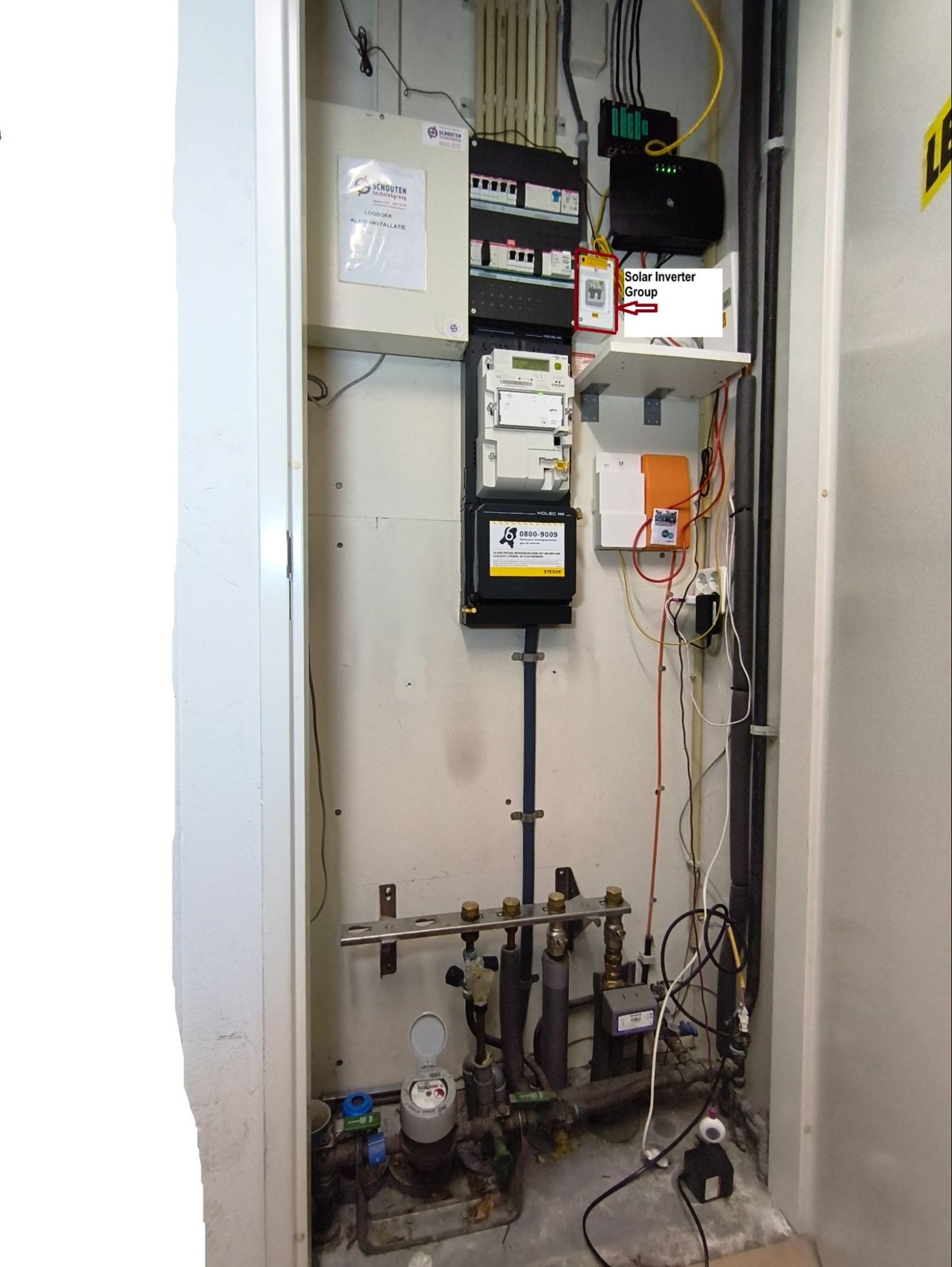
Grid connection 3 × 25 A, smart meter with a P1 dongle (power per phase visible).
Main switch ABB 3-pole 40 A.
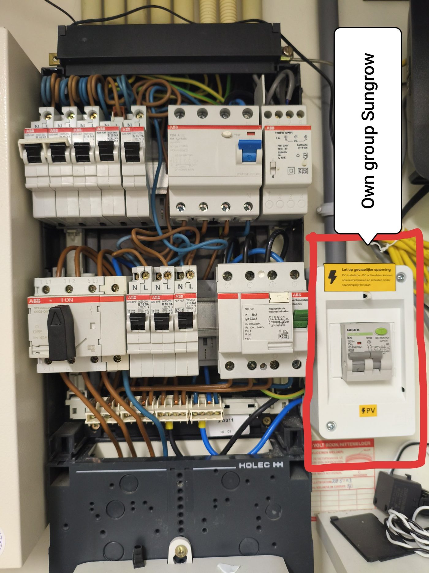
Group panel Holec/Hafonorm (2003). Row 1: RCD ABB F204 A 40 A/30 mA with a 2-pole cooker group + 3 groups B16. Row 2: RCD 40 A/30 mA with 3 groups B16 (smoke detectors). Only 1 free module per row → full.
PV: separate small box with a Noark RCBO B20 30 mA → Sungrow SH3.6RS. Stays as it is.
I'll find the phases with the P1 meter: kettle on → which phase jumps; cooker zones one by one → the two cooker phases; sunny moment → the phase with negative power = PV.
Strip from the schematic: existing + new sub-panel.
New heat-pump sub-panel "WP-kast" (E1), next to the PV box
Main switch ABB 40 A (outputs)
 └── feed 6 mm²: L-a, L-b, N, PE ──► E1 WP-kast (surface box, 12 modules)
       ├── E2 RCBO C16 30 mA type A (L-a) ── E6 kWh meter ── 3 × 4 mm² ── E5 isolator ── Haier AW062
       └── E4 RCBO 20 A 30 mA type A (L-b) ── 3 × 4 mm² (≤ 25 m) ── ATW-A03N
                                              ├─ 3-way valve, pump 2 (CN37), sensors
                                              └─ built-in relay (2/4) ── 3 × 2.5 mm² ── element 2.5 kW
Code
Part
Why
E1
Surface box 1 row, 12 modules, IP40
Panel full; existing RCDs stay untouched
E2
RCBO C16, 30 mA, type A, 1P+N, 6 kA
DB: max. fuse 16 A, MCA 13.5 A, cable ≥ 4 mm². Phase L-a = the phase without the cooker.
E4
RCBO 20 A, 30 mA, type A, 1P+N
ATW p. 7: "with tank heater" 20 A, 4 mm². Phase L-b (a cooker phase); the element runs only for anti-legionella/backup.
E5
Isolator ≥ 25 A, IP65, lockable
At the outdoor unit (NEN 1010)
E6
1-phase MID kWh meter on E2 (HomeWizard or Eastron SDM120)
Real SCOP + short-cycling check; pulse for CN52? (V6)
–
Cables: 3 × 4 mm² outdoor (XMvK/YMvK or H07RN-F, V11) · 3 × 4 mm² to the ATW · 3 × 2.5 mm² to the element · P/Q 2 × 0.75 mm² shielded · 2-core BDR91 → CN13
Worst-case load (cold winter evening, everything on): L1 ≈ 21 A, L2 ≈ 20 A (+ 11 A element only during the anti-legionella hour), L3 ≈ 17 A (heat pump at max. 3.1 kW ≈ 22 A). The installation company builds, connects and tests the sub-panel (ISDE).
7. Outdoor unit
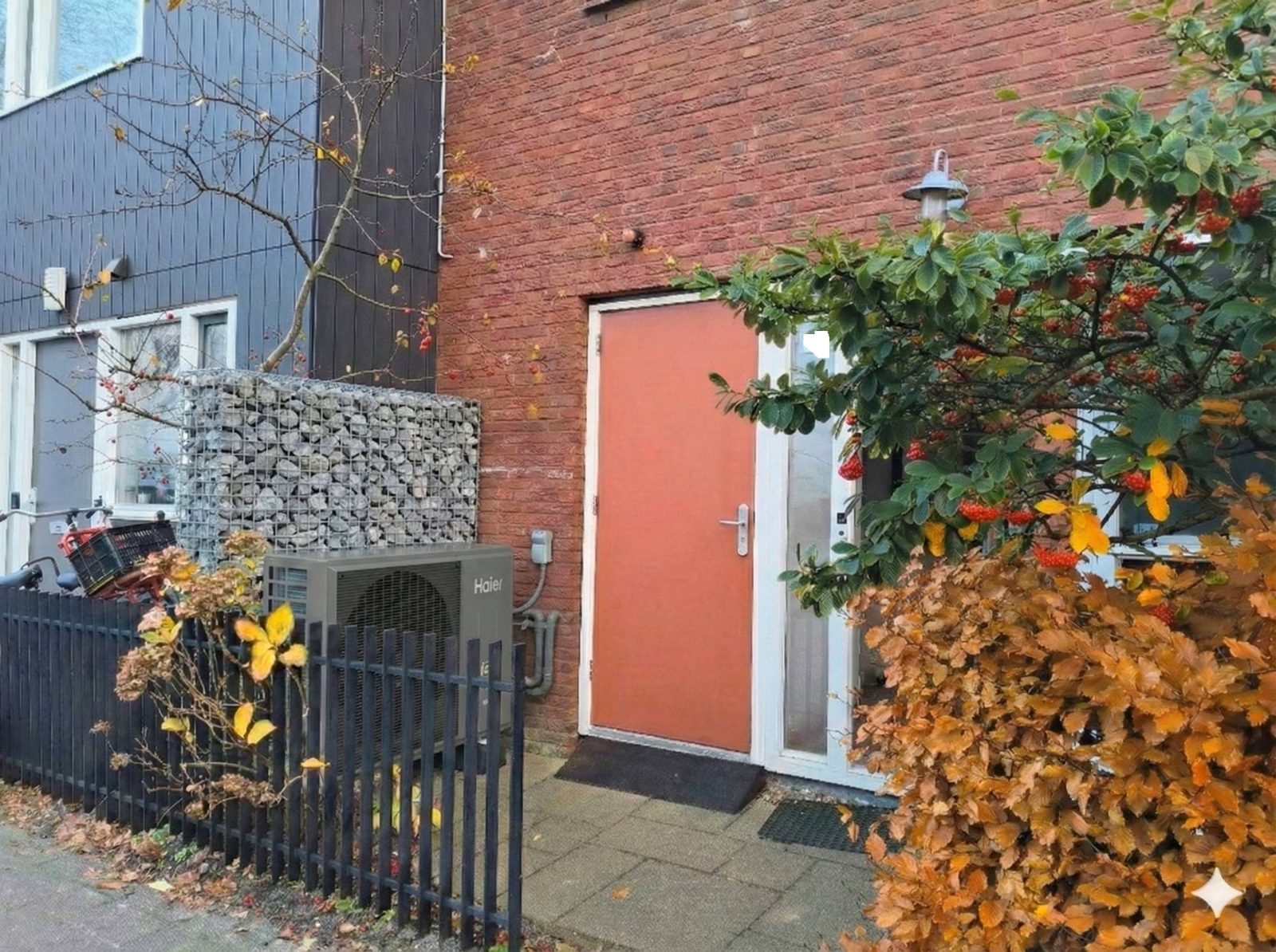
Planned position of the Haier against the front facade, behind the fence and next to the storage-room door.Ground-floor plan (front). The tank and buffer (two circles) go in the storage room, right behind the outdoor unit, so the pipes into the house stay short.
Location: front of the house; the neighbours agree.
Noise: limit 40 dB(A) at night / 45 dB(A) by day at the property boundary (Bbl). AW062 sound power 58 dB(A) → Quiet mode 22:00–07:00, on the 6 supplied rubber dampers and a raised stand.
Clearances (IM p. 20): ≥ 250 mm behind the unit, ≥ 1,000 mm free in front of the fan, top open.
R290 (IM p. 25): not under a window or door, not near basement windows, ventilation openings or a street drain, not near sockets or outdoor lights.
Condensate and defrost water to a gravel soak-away, not onto the pavement (ice) and not into a drain close to the unit.
Pipes through the front facade with UV-resistant insulation ≥ 30 mm; anti-freeze valves low and close to the unit. The Haier has ≈ 66 kPa available head at 1.03 m³/h (loop 1 needs ≈ 25–35 kPa).
8. Parts and cost
The installation company installs everything (required for ISDE); I may buy the materials myself. ✅ = my pick. Prices incl. VAT, checked 2–4 November 2026.
Not included: the installation company's labour, the optional drinking-water expansion vessel (€40–60), floor-heating phase 2 (≈ €175–540). Already in the boxes: Y-filter, 3 sensors, controller, ATW-A03N, 6 rubber dampers, drain elbow (Haier); T&P valve (WT200V); magnesium rod (WT60V).
Planning: 3–4 quotes this week. Order tank and buffer as soon as an installer accepts customer-supplied Haier tanks. Other parts before ≈ 10 November. No delivery date before ≈ 20 November → Dutch fallback. Goal: warm before 20 December.
9. All open points in one table
What no Haier document settles. Points with a question number are on the forum; the rest I settle myself or with the installer.
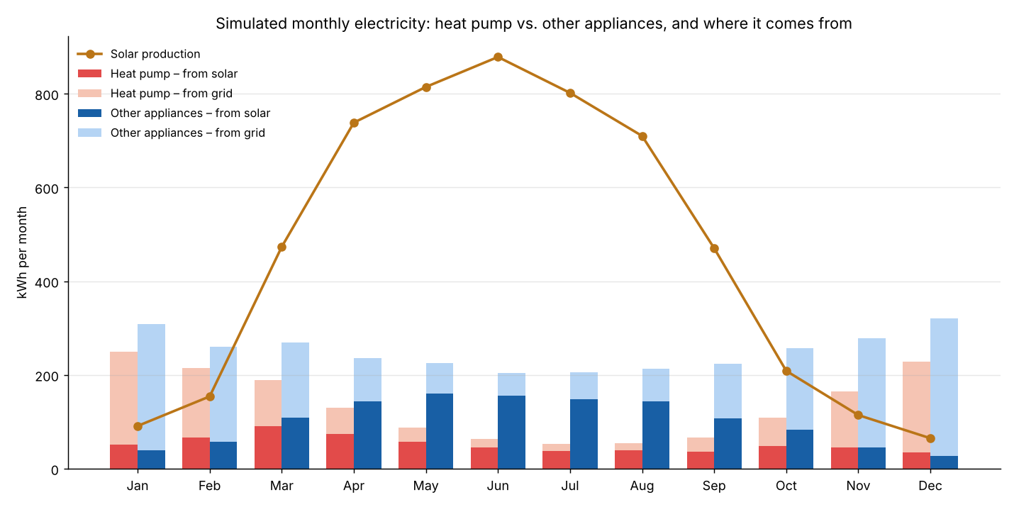
Hour-by-hour simulation of an average year with the real monthly yield (5,520 kWh), KNMI climate normals for the region, 3,470 kWh space heating and ≈ 1,195 kWh tap water:
Heat pump ≈ 1,600 kWh/year, ≈ 75 % of it in November–March.
Heating the tank between 11 and 15 h: 627 kWh (39 %) directly from the panels, against 305 kWh when heating in the evening. Hence V5.
Net metering (saldering) ends on 1 Jan 2027, so direct self-consumption becomes more important.
In December/January the panels cover only 15–20 % of the heat pump.
Simulation per month.
11. Photos and drawings
AI impression of the end result (not a photo).AI impression with numbers (not a photo; see notes).Front facade from above with the rooms.Outdoor-unit position at the front facade.Floor plan: tank and buffer in the storage room.Meter cupboard now. 1 cold, 2 hot, 3 supply, 4 return. The VC8015 is removed.Old Eneco delivery set (before removal).Meter cupboard overview with the PV group.Group panel (2003): full, PV on its own RCBO.Specialist's sketch (3 Nov): same principle.Haier AW062MUGHA (product photo).WT200V: ports and heights (Haier).WT200V installation diagram (Haier).WT60V: 4 water ports DN32, air vent, measuring port.WT60V: Ø 482 × 738 mm.
12. Reply template
Want to help? Copy this template, paste it into your reply in the forum thread, and fill in only the questions you know something about. Just delete the rest. That way I can find the answers per question. Many thanks in advance!